Electrical safety - Identifying mismatched d.c. connectors in solar PV installations
This information bulletin provides electrical installers, inspectors and auditors guidance in identifying mismatched d.c. connectors in solar PV installations to ensure compliance and safety requirements are met.
Since July 2012 Australian Standard AS/NZS 5033:2021 - Installation and safety requirements for photovoltaic (PV) arrays requires solar PV installers to only mate d.c. connectors from the same manufacturer.
Investigations nationally show the cause of failure in many solar PV installations was the result of different brands of solar d.c. cable connectors mated together.
Using mismatched d.c. connectors is considered a poor installation practice which has the potential to cause major damage with a safety risk to occupants due to fire or smoke inhalation.
In the Northern Territory, there had been incidents of fire within solar PV systems reported due to mismatched d.c. connectors failing.
These incidents of non-compliance indicate either:
- A misunderstanding within the electrical industry on how to identify a mismatched d.c. connector; or
- A lack of care to ensure compliance to the minimum safety standards.
Installing or certifying a solar system with mismatched d.c. connectors is a breach against Section 29 of the Electrical Safety Act 2022 and Section 26 of the Work Health and Safety (National Uniform Legislation) Act 2011. Enforcement action may be taken by NT WorkSafe where a breach of these Acts has been identified.
Identifying mismatched d.c. connectors.
How can we ensure mismatched d.c. connectors are not mated together?
It can be difficult to identify the brands of connectors on the panel as they all look very similar. It is important to ask your supplier or check the panel spec sheet for the details of the connector.
Guidance for installers (licensed electrical workers)
Ensure the same type of connectors from the same manufacturer are used, and the manufacturer-approved crimping tool is used for the connections.
Crimping
Some failures have been caused by a poor cable crimp, either by a set of pliers or a non-approved crimping tool.
To satisfy AS/NZS 5033:2021 clause 4.3.9.1, a manufacturer-approved crimping tool must be used to ensure the connection is crimped to the required pressure (Nm) using the method (technique) as required by the manufacturer. This will ensure the connection is rated for the designed current carrying capacity.
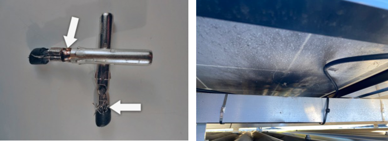
All d.c. connectors carry significant direct current energy; therefore it is very important crimping is done correctly.
A poor joint with a d.c. cable can lead to arcing, and as solar panels are energised by the sun, it will continue arcing while the sun shines.
Don’t risk it!
If the panel has different connectors than the ones you carry, ask your supplier for spare matching connectors.
Ideally, you will find matching connectors from one PV panel to the next which have been fitted and supplied by the PV panel manufacturer.
The d.c. connectors will be located at the start of the return d.c. cable from the end of the PV array, or from a top PV array to a lower PV array, between split PV arrays, and at the d.c. isolator.
Note: You must also check d.c. connectors at the inverter.
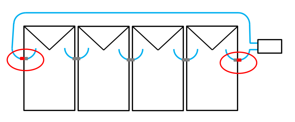
Identifying DC connectors
It is a clear requirement in the standard that only connectors of the same type from the same manufacturer can be mated together.
It is the responsibility of the licensed person to ensure all connectors comply with this requirement.
Tips to identify different d.c. connectors:
- Look at the ‘O’ ring on the male POS connector. Some have different colours, some have two ‘O’ rings. If the ‘O’ ring on your panel doesn’t match the connector you are fitting, then it is probably a mismatched connector.
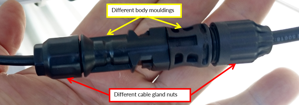
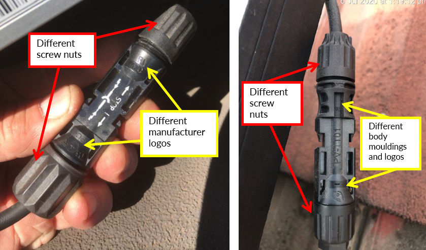
- Look at the screw nut on the cable gland at the end of the connector. The shape varies from brand to brand, this may be an indicator of a mismatched connector.
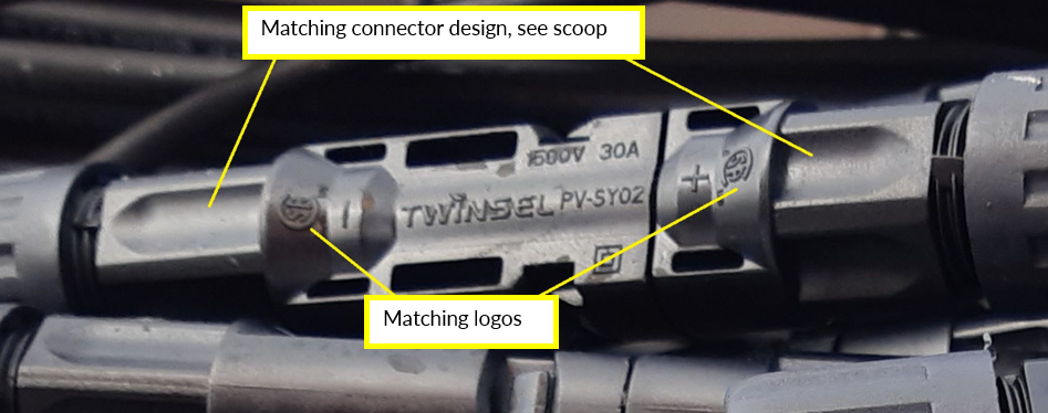
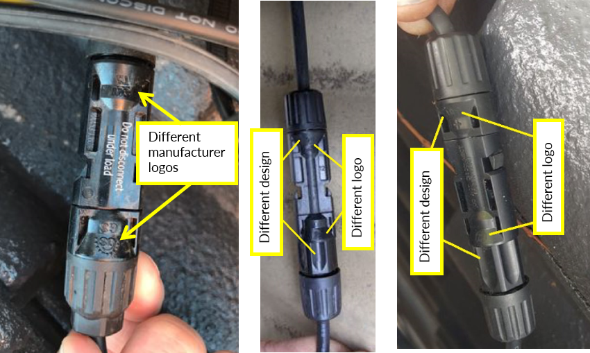
- Look at the contour of the body mouldings. Manufacturers use the same design on both the POS and NEG connectors, this is easily recognisable as a mismatched connector.
- If in doubt, verify the connector by looking at the small manufacturer’s logo or symbol on the connector body. If they match, you can be sure they are from the same manufacturer.
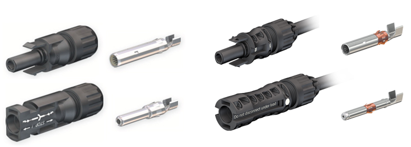
Examples of different d.c. connectors
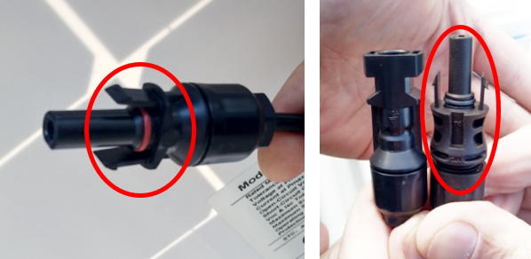
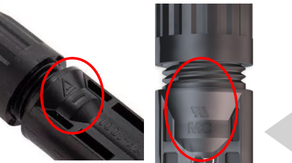
Example of a compliant, matching d.c. connector
Examples of mismatched d.c. connectors
Expansion to previous requirement
The previous requirement specified that the plugs and sockets had to be the same type and from the same manufacturer.
This requirement allows different plugs and sockets from the same manufacturer to be connected together, provided the manufacturer has designed them to be mated together. An example of this is from connector manufacturer Staubli. Their d.c. connector brands MC4© and new version MC4-EVO2© have been designed and tested to be compatible for connection together.
Staubli instructions must be followed when mating these two connectors. The Staubli specifications state the MC4 has a maximum voltage of 1000 V DC whilst the MC4-EVO2 has a maximum voltage of 1500 V DC, the rated currents are the same. Therefore, when used together the application must not exceed the lowest rated voltage of the connectors.
Additional information
Information bulletin
Code of Practice
Acknowledgement
This document was developed with guidance and original content from Energy Safe Victoria (esv.gov.au).